
Value
Structural Characteristics
Each arch of the bridge consists of smoothly curved skeleton lines, its end support points restrained so that when a vertical load is applied to the curved surface of an arch, a horizontal reaction force is generated in the support points. When subjected to free vibration, each arch prominently shows the symmetric mode of deformation inherent to an arch structure, as well as the asymmetric mode of deformation. In view of these characteristics, each of the central three spans of the Kintaikyo Bridge is considered to have an arch structure, and is the prototype of an arch bridge made of large-section, glue-laminated timbers. Each arch, resiliently retained at the end support points, provides different rigidities against small rotation and large rotation.
Materials
Timber
As mentioned in Section 2-1-2, the kinds of timbers used for this bridge, locations of their use, sizes, and other details are specified in the ancient drawing created in 1699. These specifications are followed even today.
The skill of identifying timber characteristics, cultivated over years through the Japanese wooden culture, enabled the use of appropriate types of timber in the right places, taking advantage of the characteristics of hard timber, flexible timber, decay-resistant timber, smooth timber and so on. The resulting Kintaikyo Bridge represents the essence of the wooden culture.
Stone
The stones for the substructures of the Kintaikyo Bridge were taken from quarries on Mt. Iwakuni. Though the substructures were washed away by a flood in 1950, most of the stones were collected and reused for restoration, together with the stones of substructures that had escaped destruction. As a result, most of the stones in the present bridge substructures are those of the original bridge.
Iron
The Kintaikyo Bridge is valued as an artifact of wood, stone and iron. When the bridge was renovated recently (in work called the Heisei era renovation), engineers attached particular importance to nails (Japanese nails). Each nail was carefully manufactured by forging a special metal (i.e., heating and hammering metal material), developed for use in crafting the nails to be used in the latest reconstruction of Yakushiji Temple. The developed metal has low concentrations of carbon, manganese etc. and provides the anti-corrosion property of old Japanese iron.
Bridge Engineering
Girder assembly technique
The Kintaikyo Bridge, a five-span wooden bridge, is 193.3 m long and 5 m wide (4.3 m effective width of road). The three central spans are arch bridges, and the two end spans are warped girder bridges. The span of each arch bridge is 35.1 m; that of each girder-bridge is 34.8 m.
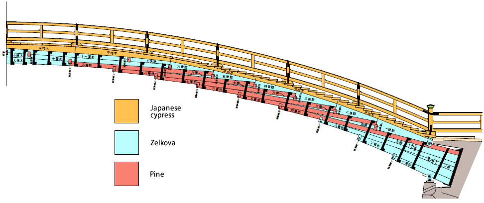 |
| Fig. 3: Structure of Bridge Girder |
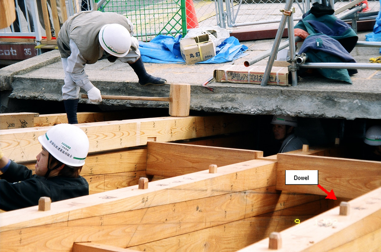
The girder of each span comprises 1st through 11th girder members, a large ridge board and a small ridge board (see Fig. 3). The rear ends of the 1st through 4th girder members are inserted and bolt-clamped in the iron shoe mounted on the upper part of the substructure. The 5th through 11th girder members are longitudinally staggered so that each member protrudes by approximately one-third of its length from the girder member immediately beneath it. Girder members are sequentially installed in this way from each end of the span. A large ridge board is mounted between the 9th girder members from both ends; a small ridge board is mounted between the 10th girder members which are installed on the large ridge board. A long thin wedge is inserted between each overlapping girder member, causing the front-end portion of each member to bend slightly downward, so that an arch is formed by all girder members. To prevent girder member displacement, dowels (Photo 11) are placed in the surface of each girder member that contacts other girder members. The overlapping girder members are bound together using pairs of C-shaped hoop irons, called girder binders, which are positioned on the lateral sides of the girder members. This assembly technique, unique to the Kintaikyo Bridge, is called voussoir arch method.
Fig. 3 shows the girder assembly structure adopted for the original bridge, constructed in 1673. Ten years later, in 1683, V-shaped saddle bars (unique to the Kintaikyo Bridge) were installed, and auxiliary bars were installed along each arch rib (Photo 12), to complete the present girder assembly structure.
 |
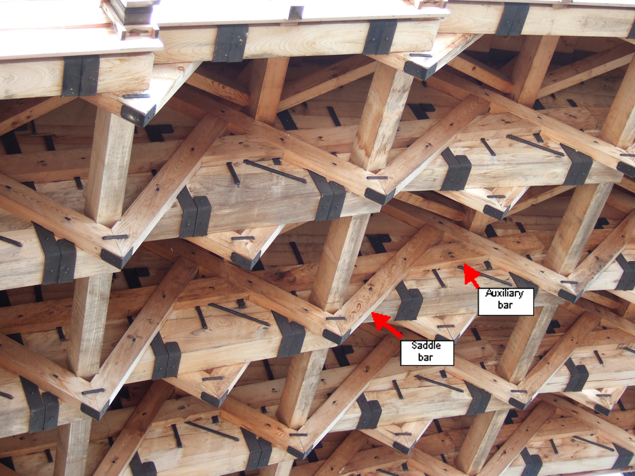 |
| Photo 11: Installed Dowels | Photo 12: Saddle Bar and Auxiliary Bar |
Construction process
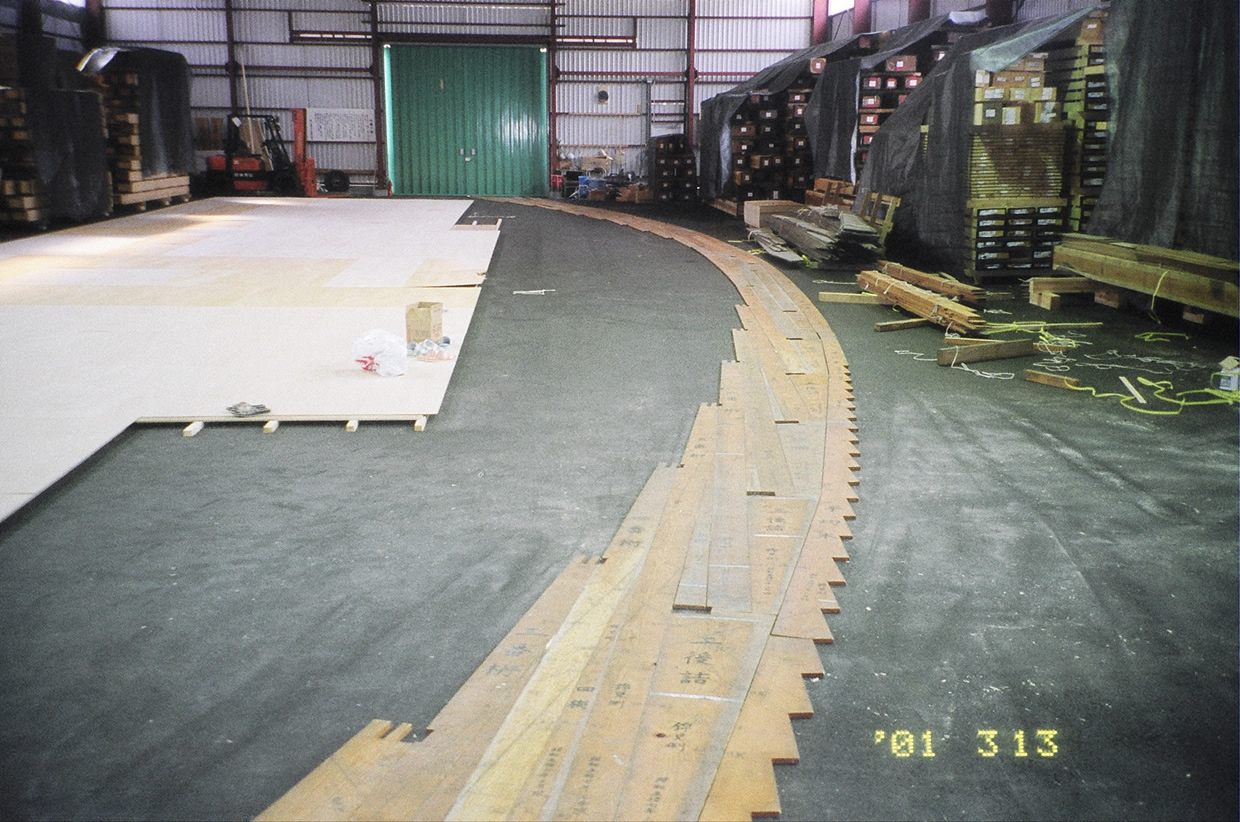
Full-scale drawing
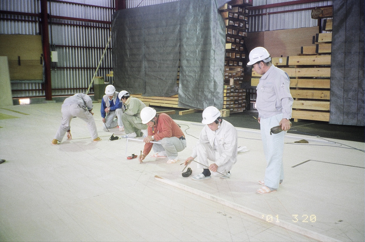
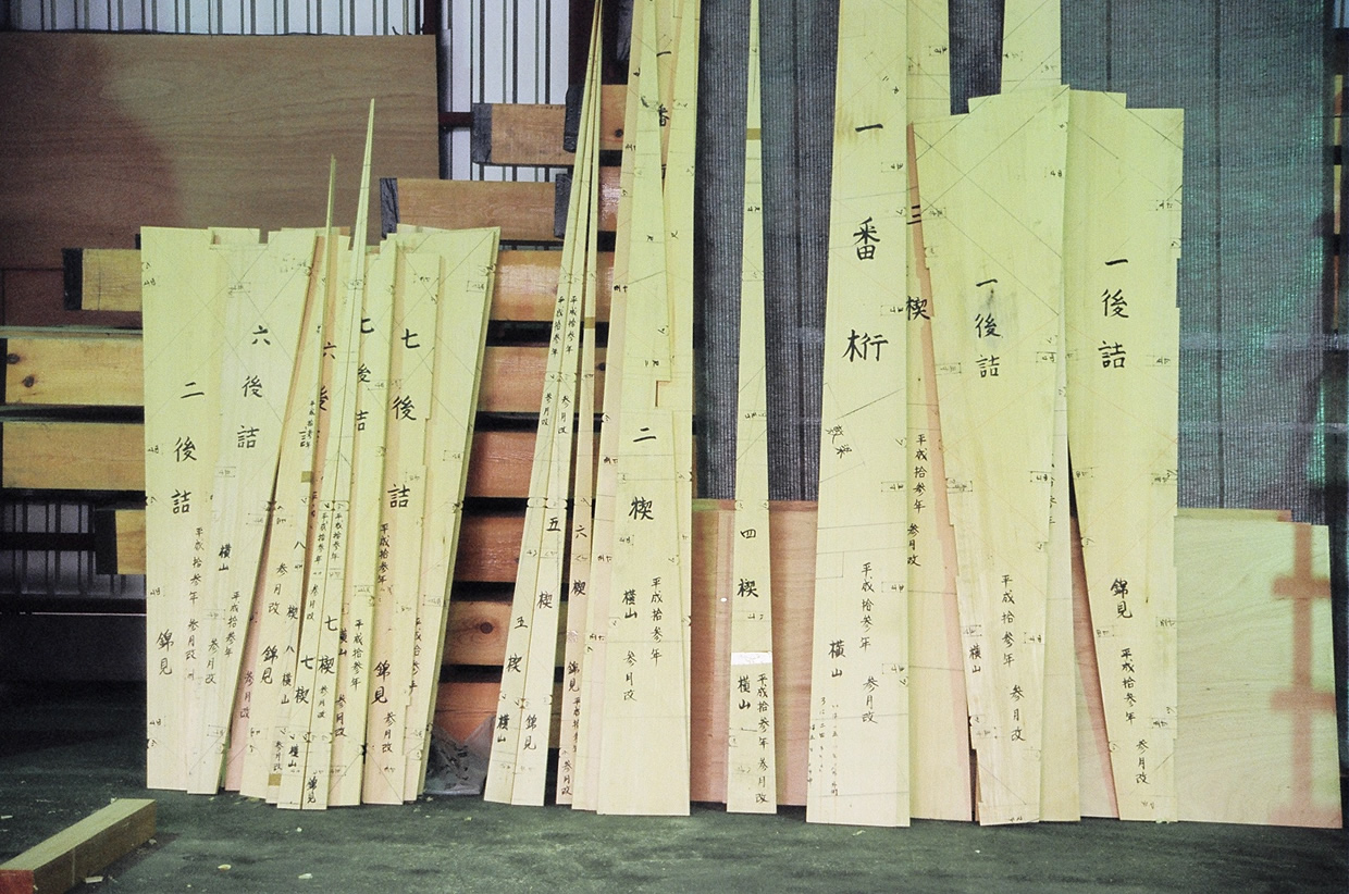
Prior to timber-working, a full-scale drawing is created (Photo 13) based on the actual arch dimensions; all girder members and other members are drawn on it. The templates for respective members are then produced from the full-scale drawing (Photo 15).
 |
 |
| Photo 13: Girder Members Are Drawn | Photo 14: Template Produced in 1929 (For Reference) |
 |
|
| Photo 15: Templates Produced for Heisei Era Renovation |
Timber-working
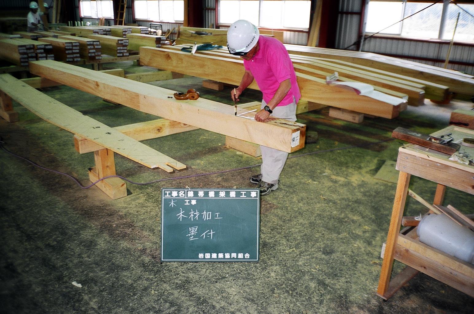 |
| Photo 16: Marking on Timbers |
After template production, each timber intended for a girder beam, marked with an appropriate template applied to the timber, is cut and machined to produce a girder beam (Photo 16).
Temporary assembly on land
 |
| Photo 17: Bridge Girder Assembled on Land |
Upon completion of timber-working, a bridge girder is temporarily assembled on land. Temporary assembly on land was also conducted before construction of the original bridge, as well as before each subsequent renewal project. The objective is to make fine adjustments to the assembly, so as to facilitate and expedite site work (Photo 17).
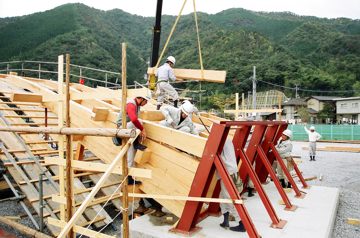
Site work
 |
| Photo 18: Installed Crossbeams |
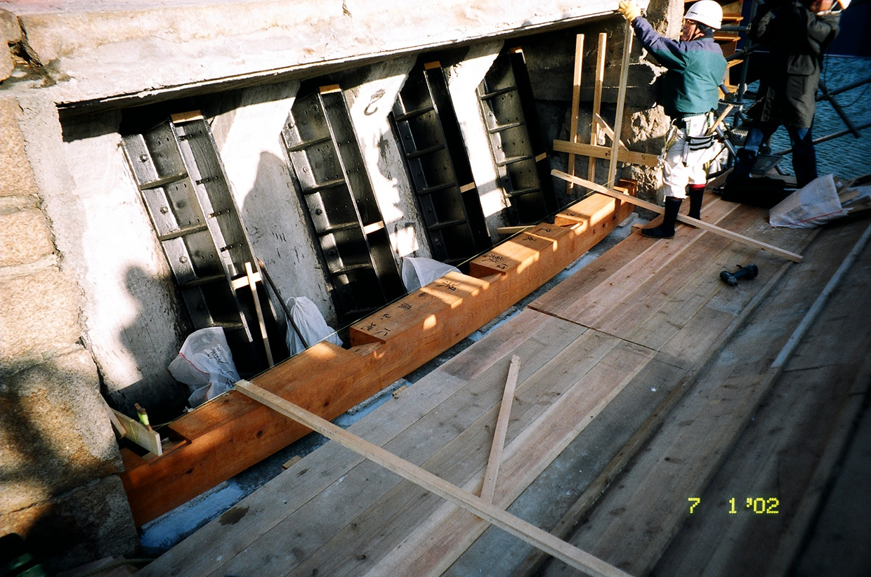
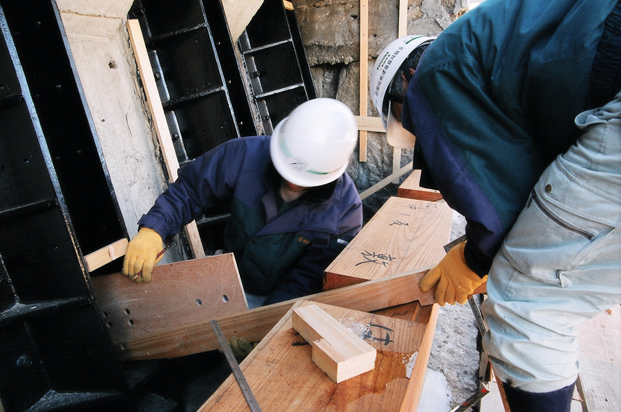
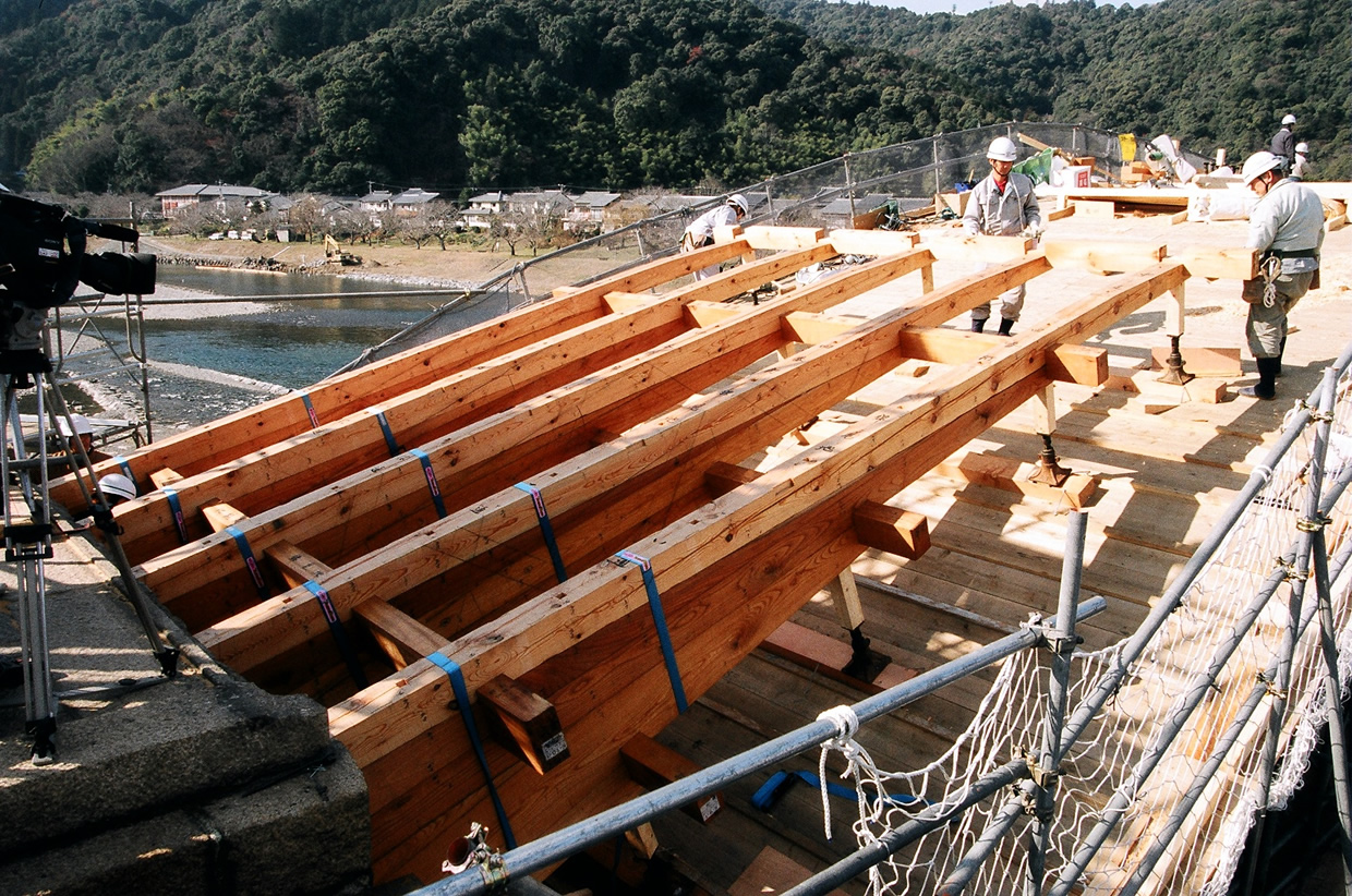
Crossbeams that support the girder are installed (Photo 18); the 1st girder member is then mounted thereon at the angle of inclination shown in the ancient drawing (Photo 19). The 1st through 4th girder members are then inserted into the iron shoe and clamped with bolts (Photo 20). The 5th through 9th girder members are stagger-mounted so that each girder member protrudes forward from the girder member immediately beneath it. After installation of the 9th girder members from both ends, a large ridge board is mounted between the two 9th girder members, to connect the trains of girder members approaching from both ends. The 10th girder members are then mounted. After a small ridge board is installed between the 10th girder members, the 11th girder member is mounted. The girder members thus mounted are bound together using girder binders. Finally, post-packing is applied, and averaging wood members are installed to complete the girder assembly.
 |
 |
| Photo 19: Angle Adjustment of 1st Girder Beam |
Photo 20: 1st through 4th Girder Members Fixed to Iron Shoe |
 |
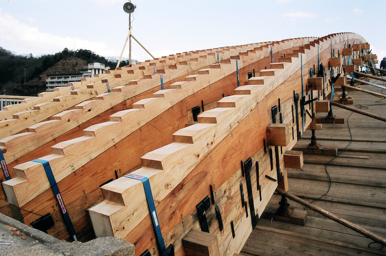 |
| Photo 21: Bridge Girder Assembled on Site | Photo 22:Post-Packing and Averaging Wood Members Installed on Girder Assembly |